Japan’s revised Feed-in Tariff Act mandates the installation of PCSs with output control functions to secure a stable power supply while connecting PV power plants to the grid. The “Next-generation Bidirectional Communication Output Control Emergency Demonstration Project” was opened for bidding in 2015, and Hitachi, Ltd. was selected to develop a PCS that can achieve real-time output control for large-scale PV power plants. The system is configured with power information devices that transmit and receive information with the utility’s integrated control center, a remote station that exchanges input/output with power distribution equipment, a group of controllers that control the monitoring and control network for power generation equipment, and multiple PCSs with output control functions. On-site demonstration tests confirmed that it is possible to control power output, as directed by control commands from Kyushu Electric Power Co., Inc., by applying this system to Oita Solar Power Corporation’s in-service PV power plant.

Photovoltaic Power Generation Business Department, Renewable Energy Solutions Division, Power Business Unit, Hitachi, Ltd. Current work and research: Promoting sales of components of large-scale photovoltaic power generation systems. Society memberships: The Japan Society of Mechanical Engineers (JSME).

Photovoltaic Power Generation Systems Department, Power Production Management Division, Power Business Unit, Hitachi, Ltd. Current work and research: Systems design of photovoltaic power generation systems.

Photovoltaic Power Generation Systems Department, Power Production Management Division, Power Business Unit, Hitachi, Ltd. Current work and research: Systems design of photovoltaic power generation systems.

Photovoltaic Power Generation Systems Department, Power Production Management Division, Power Business Unit, Hitachi, Ltd. Current work and research: Systems design of photovoltaic power generation systems. Society memberships: IEEE.

Power Electronics Design Department, Power Electronics Division, Industrial Products Business Unit, Hitachi, Ltd. Current work and research: Development and systems design of power conditioning systems for photovoltaic power generation.
Power Electronics Design Department, Power Electronics Division, Industrial Products Business Unit, Hitachi, Ltd. Current work and research: Development and systems design of power conditioning systems for photovoltaic power generation. Society memberships: Certified P.E.Jp (professional Engineer, Japan),and The Institute of Electrical Engineers of Japan (IEEJ).

Energy Management Systems Research Department, Center for Technology Innovation – Energy, Research & Development Group, Hitachi, Ltd. Current work and research: Research and development of large-scale power conversion systems. Society memberships: IEEE and IEEJ.
When it comes to renewable energy, the natural energy sources of photovoltaic (PV) and wind power are strong candidates for both the effective utilization of domestically produced energy and countermeasures for global warming and the establishment of a low-carbon society. At the same time, these energy sources also suffer from the disadvantage that their supply capacities are influenced by the weather, and variations in both sunlight and wind make it difficult to control capacity to meet the power demand.
The introduction of renewable energy in Japan, including PV and wind power, has expanded rapidly since the feed-in tariff (FIT) scheme for purchasing renewable energy at a fixed price commenced in July 2012. As a result, there were concerns about connecting previously certified PV power plants to utilities’ grids. Since there is less use of air conditioning during the spring and fall periods of sunny weather, the generation of power from natural energy sources such as PV and wind might exceed the power consumed in the daytime. The concern was that this would cause the supply and demand of electric power to become unbalanced and, in the worst-case scenario, make it impossible to supply electricity in a stable fashion(1). Wanting to avoid this problem, some utilities stopped answering applications to connect to their grids. However, in order to avoid interfering with the introduction of renewable energy, renewable energy power producers accepted unlimited output control in excess of 30 days on the condition that a finely tuned output control system would be introduced for the power generation equipment. The utilities then resumed responding to applications to connect to their grids.
Hitachi, Ltd. participated in the Next-generation Bidirectional Communication Output Control Emergency Demonstration Project carried out by Kyushu Electric Power Co., Inc. by developing a system for implementing real-time output control for PV power plants that interconnect with large-scale, high-voltage power grids. This article presents an overview of this system.
PV power plants control output based on output control commands received from a utility. Figure 1 shows how control commands are received from the utility. In the case of a PV power plant that is interconnected with a high-voltage power grid (66 kV or higher), output control commands are received via a dedicated line that connects directly to the utility(2). Output control commands are sent as percentages, with the entire capacity of the power plant as 100% (e.g., to control a power plant with a plant capacity of 10 MW so that it outputs 5 MW of electricity, the power company sends the command “50%” to the power plant).
Figure 1 — How PV Power Plants Receive Control Commands from a Utility
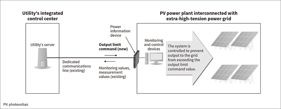 The utility sends output control commands to each piece of power generation equipment over a dedicated line.
Figure 2 shows the PV power plant output control system developed by Hitachi. The system configuration includes three power information devices [cyclic digital data transmission (CDT) 1, CDT2, and hybrid CDT (HYB) devices], which transmit and receive information between the system and the utility’s integrated control center; a remote station that exchanges input/output with the power distribution equipment; a group of controllers that control the monitoring and control network for the power generation equipment; and multiple power conditioning systems (PCSs) with output control functions.
Figure 2 — Configuration of PV Power Plant Output Control System for Interconnection with High-voltage Power Grids
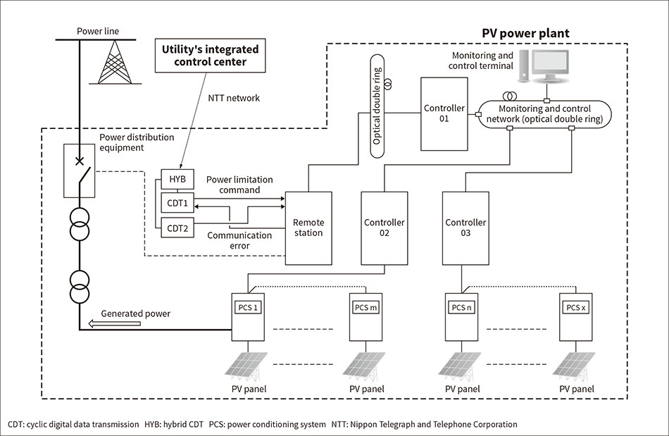 In addition to the two CDTs and the HYB, the configuration also includes a remote station (a computer that exchanges input/output with the power distribution equipment), controllers (computers that control the monitoring and control network while converting output control signals from the utility to PCS output limiter values and sends them to the PCS), a monitoring and control terminal (a terminal that monitors the state of plant power generation and alarm information using batch monitoring, and which is used to control the power generation equipment with manual input).
Although conventional PV power plants do not perform output control, they send information to the integrated control center such as the power generation equipment’s output values and whether or not the power generation equipment was interconnected with the grid. Therefore, they were equipped with a single CDT. However, performing output control requires receiving output control commands and other information from the integrated control center, so two CDTs are used in parallel. In addition, bidirectional communication with the power generation equipment is implemented by adding an HYB to integrate information for transmitting and receiving over a single dedicated line. The power control commands input via the CDT are converted at the remote station into a signal format that can be handled by the computers (controllers 01 to 03) that are connected to the monitoring and control network inside the power plant.
Figure 3 shows an example of how an integrated control center command value is converted into a maximum output limiter value to be sent to each PCS with output control functions. Since the command value represents a percentage of the equipment’s entire capacity, as described previously, it is converted into a kilowatt figure to be issued to each maximum output limiter in each of the equipment’s PCSs (rated capacity of 500 kW). The output control speed is stipulated to be adjustable within the range of 100% to 0% output (0 to 100% output), with an output change time in 1-min intervals between 5 to 10 min(3). To synchronize the inverter output tracking of the PCS with output control functions to this speed, this rate of change is created by the controllers in a staircase shape (ramp) and distributed to each PCS with output control functions from controllers 02 and 03, thereby issuing instructions for the PCS maximum output limiter.
Figure 4 shows how PV panel output is controlled by the PCS with output control functions based on the maximum output limiter value. Since the PCS with output control functions has a limiter to limit alternating current (AC) power output, it is possible to change the maximum PCS power output to a value within the rated output by giving the limiter value as a parameter. The maximum output limiter values input from the controllers is stored in the AC control part of the circuit (also shown in the figure), which controls output to ensure that it does not exceed those values.
Generated power is actually controlled by maximum power point tracking (MPPT, also shown in the figure). Figure 5 provides an overview of this process. MPPT control adjusts the photovoltaic (PV) panel voltage (= PCS input direct current voltage), basically operating with the PV panel’s power at maximum. The amount of output that can be produced at the same time on the AC side, however, is determined based on the limit value of the limiter in the AC control part of the circuit. For this reason, even if there is a bump above this limiter value in the PV panel’s power-voltage (P-V) characteristics at a certain time due to the level of sunlight, the system is controlled to ensure that excess power is not produced. Instead, power is produced with a voltage at the intersection of the limiter value and the P-V characteristics curve.
Figure 3 — Example of Converting the Integrated Control Center’s Output Control Command Value to the PCS Maximum Output Limiter
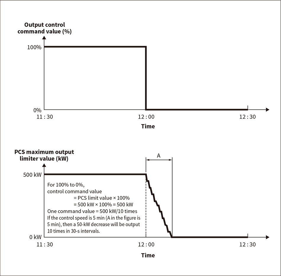 Although output control command values are issued in the form of percentages, the controllers convert them to actual maximum output values for the PCS.
Factory verification tests confirmed that it is possible to control output with a configuration that actually couples a single development PCS with a monitoring and control device. Figure 6 shows an example of the test results. The accuracy of the PCS with output control functions must be within ±5% of the rated output(3), and tests confirmed that this was achieved.
Figure 6 — Example of Plant Test Results
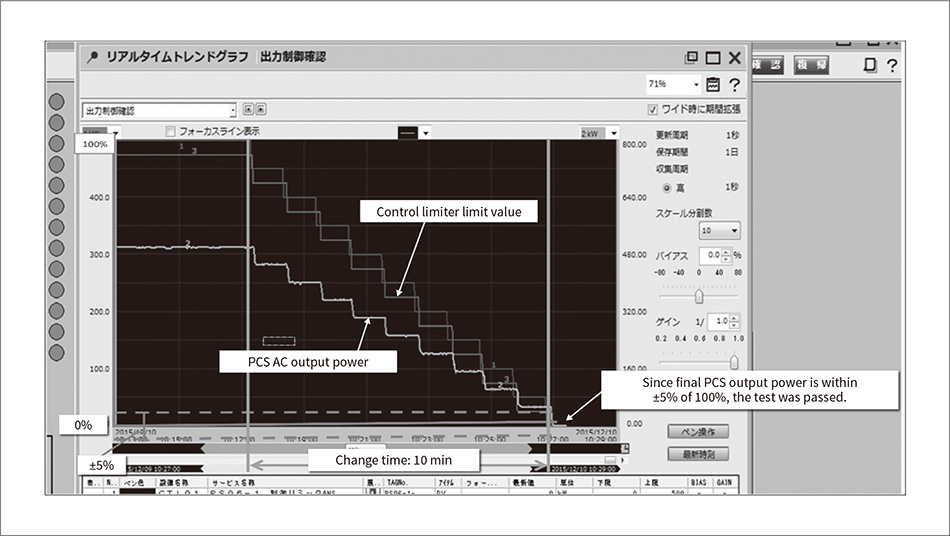 This figure shows an example of the monitoring terminal screen results displayed when controlling output from 100% to 0% in 10 min. Control successfully stays within ±5% of the rated output (500 kW).
On-site verification tests conducted in Kyushu confirmed that output control commands from Kyushu Electric Power’s integrated control center can actually be received by operational power generation equipment in order to control power output. During the on-site verification, Hitachi enlisted the cooperation of Oita Solar Power Corporation’s PV power plant, for which Hitachi had won an order for everything from design to procurement, fabrication, installation, and commissioning, and applied this newly developed system. Table 1 provides an overview of Oita Solar Power’s PV power plant(4).
Figure 7 shows an example of the results obtained from these tests(2), which confirmed the ability to control power output based on control commands received from Kyushu Electric Power. The verification tests successfully confirmed the development of a system that satisfies the technical specifications of a PCS with output control functions within the demonstration project period.
This article has presented an overview of the real-time output control system for PV power plants developed by Hitachi as part of Kyushu Electric Power’s Next-generation Bidirectional Communication Output Control Emergency Demonstration Project.
Future deployment of this system is expected to increase the interconnection of PV power plants while helping to meet the demands of the grid. Hitachi will continue working to develop solutions that can both achieve a low-carbon society and stabilize the grid at the same time.