Core Utility Products Underpinning the Social InfrastructureDevelopment of Next-generation Mechanical Testing Systems to Facilitate Use of Test Data
Highlight
Since mechanical testing systems handle various types of test data for analysis, they ideally should be able to apply technologies that use digital data that has been the focus of recent research and development work. Hitachi is working on developing next-generation mechanical testing systems that provide total support for customer evaluation testing by bringing data digitization and IoT technology together with testing systems applying high-performance measurement control technology. This article provides an overview of these next-generation mechanical testing systems and presents the hardware in the loop simulation systems and data-driven measurement control technology that comprise their core elements.
1. Introduction
Hitachi provides dynamic mechanical testing systems that assist research and development of high-speed rolling stock and help explicate how test specimens such as structures, elevated bridges, and nuclear power equipment behave during earthquakes.
Customers have always demanded mechanical testing systems that can provide highly accurate reproductions of desired test patterns such as seismic waves for earthquake-resistant design. In recent years, there are also growing expectations for digitization of acquired test data and the use of Internet of things (IoT) technology. Test specimens such as large structures and rolling stock sometimes only enable partial evaluations of the specimen itself, so finding ways of providing customers with mechanical testing systems that enable total evaluation of the items to be analyzed is a challenge for this area. Hitachi is responding to this issue by working on developing next-generation mechanical testing systems that use data to improve control performance and provide total support for customer evaluation testing.
2. Overview of Next-generation Mechanical Testing Systems
2.1 Configuration of Next-generation Mechanical Testing Systems
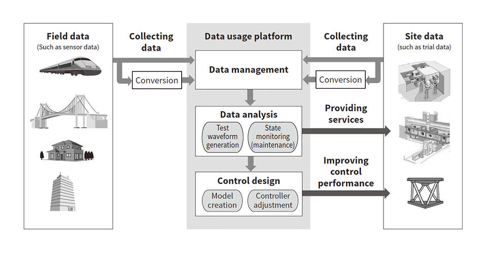
Fig. 1—Next-generation Mechanical Testing System Configuration Simulation test accuracy is improved by using a data usage platform to manage and analyze trial data acquired by mechanical testing systems installed at multiple sites, along with field data.
Next-generation mechanical testing systems provide various services by enabling data acquired by testing systems installed at customer sites to be managed and analyzed on a data usage platform (see Figure 1).
The format of the data obtainable from each site is sensor-specific, and some sensors only have analog output. Data from sensors is therefore digitized and converted to a common data format before being managed by the data usage platform’s database. Data acquired by sensors mounted on real-world structures, high-speed rolling stock, and other test specimens can also be stored on the data usage platform.
Analyzing real-world operations data from testing systems at multiple sites and monitoring equipment states can provide customers with effective maintenance and inspection services. While there are many examples of data use for maintenance functions such as state monitoring and failure predictive diagnosis, Hitachi’s next-generation mechanical testing systems also feature the application of data usage technologies to improve testing accuracy.
2.2 Data Usage Methods for Improving Testing Accuracy
Studying the best type of test patterns to use in trials done to identify the behavioral characteristics of the specimen to be analyzed can be a challenge for customers. Hitachi’s next-generation mechanical testing systems attempt to overcome this challenge by analyzing field data to create test patterns that enable effective evaluation of the behavioral characteristics of the items to be analyzed.
To enable the highly accurate reproduction of the created test patterns by the testing system, testing system actuators need to be controlled with high accuracy and responsiveness. To do so, next-generation mechanical testing systems use data obtained from each site to provide suitable control for each actuator.
3. Data-driven Mechanical Testing System Control Technology
3.1 New Mechanical Testing System Control Method
Fig. 2—Model-based Control and Data-driven Control Design Methods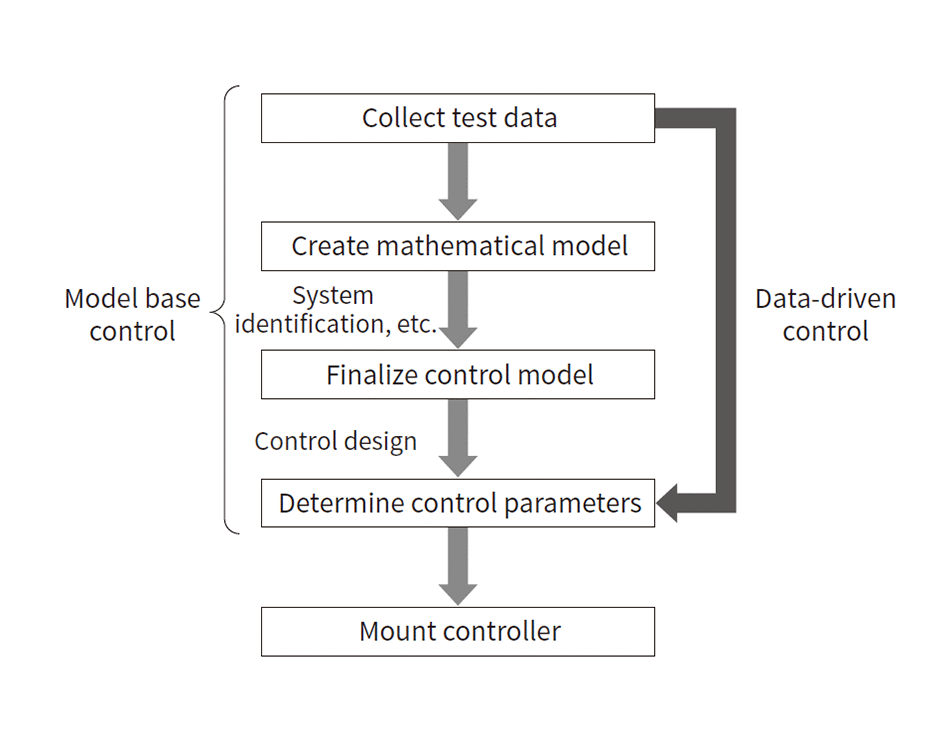 Model-based control uses test data to model the control targets and then design the control, while data-driven control uses trial data to determine the control parameters directly.
The aim of control design for test equipment is to improve the target waveform tracking characteristic. But, since many of the actuators used in test equipment have hydraulic drive, maintaining robustness is a key issue as the dynamic characteristics of hydraulic systems change due to factors such as temperature and pressure. So, to enable a good balance of responsiveness and robustness, a 2-degree-of-freedom control system combining feedback (FB) control and feedforward (FF) control was used in this development project.
To provide highly accurate control of the test equipment, the parameters of the FB control and FF control mounted in the controller need to be adjusted properly. Model-based control is the most commonly used method of adjusting control. This method builds a mathematical model of the control targets and uses the mathematical model to design and adjust the control. Model-based control requires an accurate mathematical model of the control targets. The control targets of the development project were test equipment containing test specimens. But, since the test specimens were selected by the customer operating the mechanical testing system, information about the specimens was not always available for use at the time of the control design.
The development project therefore focused on data-driven control(1) instead of model-based control for control adjustment. Data-driven control uses trial data to adjust control directly (see Figure 2). It performs control adjustment directly from the test data of the control targets and is well-suited for next-generation mechanical testing systems designed for data usage. Data-driven control only requires a single set of test data, giving it the advantage of being easier to apply on newly installed test equipment than artificial intelligence (AI)-based methods that require large volumes of data.
The development project chose the use of conventional control to guarantee control loop robustness and stability in the FB control, while using data-driven control for the FF control design.
3.2 Method for Applying Data-driven Control to Mechanical Testing Systems
Fig. 3—Method for Acquiring Data for Data-driven Control Design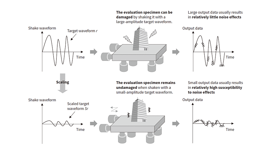 Data-driven control design usually uses a target waveform r, but shaking evaluation specimens with large amplitudes might damage them. Using a target waveform Sr that is a scaled version of the original target waveform enables test data to be acquired without damaging the evaluation specimen.
Fig. 4—FF Control Design Method Using Data-driven Control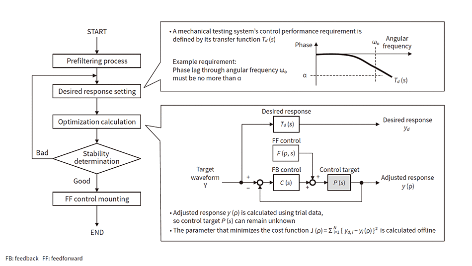 An optimization calculation is performed to minimize the difference between the desired response designed in conformance with the requirements, and the adjusted response created after FF control adjustment.
The test data required for applying data-driven control is the output data y generated when the control target has been moved by the target waveform r. In other words, for a test equipment actuator driven by displacement control, the target waveform r corresponds to the actuator’s target displacement as determined by the test pattern, and the output data y corresponds to the measurement result of the displacement sensor mounted in the actuator.
For a shaking table used by test equipment to simulate the movement of an earthquake, strong seismic waves are selected as the target waveform r. But, in this case, using target waveform r for a trial done to acquire test data for data-driven control design may damage the specimen and impede further trials.
To overcome this challenge, Hitachi devised a method for acquiring test data by using a target waveform Sr that scales target waveform r by a minute factor S (0 ≤ S ≤ 1) (see Figure 3). Selecting a sufficiently small value for factor S enables test data to be acquired without damaging the evaluation specimen. The scaled target waveform Sr contains the same frequency components as the original target waveform r, so it does not omit any information needed for control design. But a separate issue can arise as susceptibility to sensor noise effects increases as the amplitude of output data y decreases.
Hitachi has a long history of developing control for a wide range of movements with amplitudes ranging from minute to maximum. It is also experienced in acquiring information from sensors with high signal-to-noise (S/N) ratios. This background gave the company the expertise needed to reduce the effect of noise even for the output data y corresponding to the scaled target waveform Sr. This section concludes with a description of the data-driven control method used to design the FF control to be embedded in the test equipment using the acquired trial data. Figure 4 shows how the data-driven control calculation is performed. The process starts by applying a prefiltering process to the acquired test data if any noise remains in it. The desired response transfer function Td(s) is then calculated using the customer’s requirements. Next, the ρ parameter in the FF control function F(ρ, s) is determined by an optimization calculation to minimize the difference between the desired response to be implemented by the designed transfer function yd, and the adjusted response y(ρ). The next step is to determine whether the transfer function F(ρ*, s) of the FF control implemented with the calculated optimum parameter ρ* is stable. The FF control function F(ρ*, s) is mounted in the controller only if this function is stable.
Data-driven control can be applied as described here to enable optimum control parameters to be derived directly from just a single set of test data. This technology can be used to eliminate the need for trial-and-error control adjustments, enabling Hitachi to rapidly provide control performance tailored to customer needs.
4. Using HIL Simulation Systems to Integrate Real and Virtual Data
Evaluating entire structures is difficult when the evaluation specimens are large structures or rolling stock. Technology known as hardware-in-the-loop (HIL) simulation has been developed to address this issue. HIL simulations model overall behavior by using the actual item for part of the structural system and using a numerical model for the rest(2). Creating numerical models that accurately simulate real-world behavior is a key requirement for the use of HIL simulation. As a concrete example of data usage designed to improve testing accuracy, this section presents a mechanical testing system implementing HIL simulation (see Figure 5).
This mechanical testing system is composed of the test equipment containing the test specimens that are some of the items for analysis, a controller used to control the test equipment, a real-time simulator that computes numerical models in real time, and a data logger that collects test data.
The mechanical testing system operates as follows: First, the controller calculates a control command to make the test equipment move in conformance with the desired test pattern. The control command is calculated using data from displacement meters, accelerometers, pressure gauges, and other sensors installed in the actuators. The test equipment actuators operate in conformance with the control command, and the specimen is shaken in the real world. Accelerometers, strain gauges, and other sensors are also attached to the items to be analyzed, and the response generated in the specimen by the test equipment movement is measured in real time. The measured response in the specimen is digitized and sent to the real-time simulator. The real-time simulator analyzes the behavior of elemental parts other than the specimen by performing numerical calculations that use the measured specimen response as the input values or as the initial condition or boundary condition.
The component elements (specimens) that are moved in the real world and the other component elements that are substituted with numerical models are usually physically connected, so the interactions between these two sets of elements also need to be considered. To do so, the real-time simulator’s calculation results are sent to the controller, and the test pattern’s target waveform is successively revised. Changes in the behavior of the test equipment cause changes in specimen response, enabling the effect of interactions to be simulated. Accordingly, the performance of overall structure evaluations done using HIL simulation systems decreases unless the test equipment can be made to accurately track a successively changing target waveform. So, advanced control technology providing highly responsive and accurate test equipment control is needed to create HIL simulation systems. The data-driven control presented in the previous section is one control technology that addresses this issue.
Fig. 5—Example Mechanical Testing System Creating HIL Simulation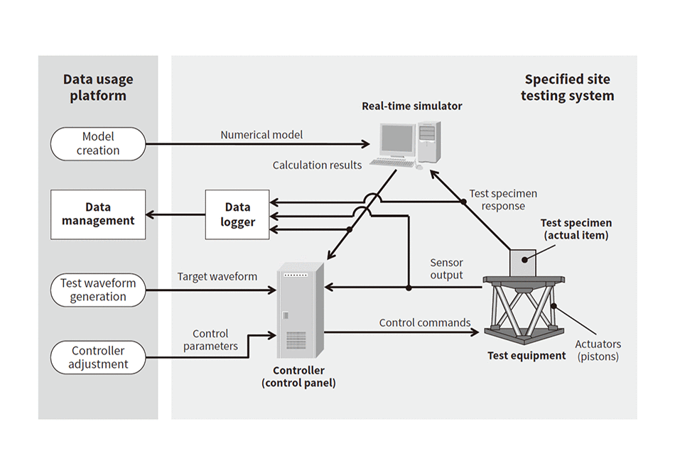 Hardware-in-the-loop (HIL) simulation can execute simulation tests of the overall behavior of large structures by using part of the actual item and modeling the rest with a simulator.
5. Conclusions
This article has presented an overview of next-generation mechanical testing systems that can provide customers with a wide range of services using data. Next-generation mechanical testing systems contain data-driven control technologies and can provide total operation support for HIL simulation systems and other customer testing systems.
Hitachi will continue to gain experience in system demonstration and verification while providing services to customers. The methods of applying the data-driven control test equipment presented in this article can also be used to improve the functions of existing testing systems, which should enable Hitachi to provide services to customers before data usage platforms are created.
REFERENCES
- 1)
- O. Kaneko et al., “Fictitious Reference Tuning of the Feed-forward Controller in a Two-degree-of-freedom Control System,” The Society of Instrument and Control Engineers, Journal of Control, Measurement, and System Integration, 4, 1, pp. 55–62 (Apr. 2011).
- 2)
- T. Watanabe et al., “135 Dynamic test for Mechanical systems with HILS concept,” Dynamics and Design Conference 2011, (Sep. 2011) in Japanese.


