Electrification Research and Development for Achieving Carbon Neutrality by 2050
Highlight
Countries and regions around the world have started to take action on achieving carbon neutrality. In the power sector, progress is being made on putting conditions in place for greater electrification, with the installation of more renewable energy capacity, the building up of infrastructure for hydrogen generation, and a shift toward local sourcing. In the transportation and industrial sectors, meanwhile, the development of innovative technologies at the material and system levels is underway to improve the efficiency of electrification, electric power, and the data centers that underpin DX. In the transportation sector in particular, there are calls for the replacement of traditional internal combustion engine vehicles with EVs, PHVs, and other electrified vehicles, looking to reach 100% adoption by 2035. Accomplishing this demands the delivery not only of economic value to owners and drivers, but also of environmental value in the move toward decarbonization. This article describes technologies for making electric motors more efficient to reduce the amount of power consumed by EVs as they become more widespread, inverter technologies for rapid charging to dispel concerns about vehicle charging, and electric power conversion technologies for electricity distribution infrastructure where there is a need for versatility while also coping with rising demand.

Introduction
Annual global emissions of carbon dioxide (CO2) are around 32 billion tons, of which Japan is responsible for about 1.1 billion tons. Direct emissions by the energy supply and generation sector make up about 40% of this and transportation is also a major contributor at approximately 17%. Together, the two industries are responsible for about 57% of all of Japan’s emissions. In addition to increasing the amount of photovoltaic, wind, and other forms of renewable energy generation to increase the proportion of energy from zero-emission sources, Hitachi’s vision for an electrified society also includes greater use of electrification to decarbonize the entire lifecycle from production and use to disposal to help achieve carbon neutrality by 2050.
Challenges for Electrification
At approximately 16%, Japan has only been sourcing a small percentage of its energy from zero-emission sources in the period since the Great East Japan Earthquake, putting it well behind others such as the European Union (approximately 57%) and China (approximately 27%). Meanwhile, countries around the world have started to take action on reducing CO2 emissions from industrial processes and distribution, with rising demand for the electrification of social infrastructure as well as a shift to zero-emission energy sources. This in turn will require further advances in easy-to-use regional energy platforms that set the scene for things like photovoltaic power generation and the trading of electric power from renewable sources (see Figure 1).
For Japan and other countries around the world to achieve carbon neutrality by 2050, each industry sector will need to set explicit targets and adopt a variety of measures to achieve them. One example is that, by the mid-2030s at the latest, all new cars sold will need to be electrified vehicles, whether they be electric vehicles (EVs), hybrid vehicles (HVs), plug-in hybrid vehicles (PHVs), or fuel cell vehicles (FCVs). The UK already plans to ban the sale of non-electric vehicles from 2030, with the USA and China to follow by 2035.
Calculating the likely CO2 emission reductions from switching to electric cars, for example, if EVs were used to replace the gasoline cars that are expected to account for 24% of all new vehicles sold globally in 2030, this would reduce emissions by about 89 million tons annually, equivalent to 8% of Japan’s total annual emissions of 1.1 billion tons. Moreover, introducing more electrified vehicles also opens up the possibility of connecting their onboard batteries together within a particular district to improve electricity system stability and to store energy from the fluctuating output of renewables, thereby increasing the percentage of energy supplied from zero-emission sources.
This article describes technologies intended to accelerate the adoption of these electrification products, including ways of making electric motors more efficient to reduce their power consumption, inverter technologies for rapid charging to dispel concerns about vehicle charging, and electric power conversion technologies for electricity distribution infrastructure that is expected to provide versatility while also coping with rising demand.
Figure 1 — Advances in Regional Energy Platforms
 The distribution of electric power is coordinated with demand by installing batteries and PCSs connected via independently operated power lines at both supply-side (renewable energy generation) and demand-side sites along with EV chargers and high-voltage inverters for air conditioning.
High-efficiency Motor Technology
Faster Motors for Higher Output Density
If electrified vehicles are to become more prevalent, then existing vehicle platforms and the need to make space for batteries mean that small size and high output densities will be required along with greater layout flexibility. While faster motor speed is one way to improve output density, the challenges to accomplishing this include the need for stronger rotors due to centrifugal force increasing with the square of speed. Also needed are ways of reducing vibrational noise, which gets worse as speed increases.
To establish a design technique that provides both rotor strength and good motor characteristics, Hitachi developed a computational technique for optimization that uses the Rosenbrock method and combines rotor stress and magnetic field analysis. Prototype testing was conducted on a 150-kW embedded-magnet synchronous motor designed using this technique to have a maximum torque of 155 N·m and maximum speed of 22,000 r/min. Figure 2 (a) shows the prototype. The predicted fracture limit for the rotor of 27,300 r/min was confirmed in spin testing. Furthermore, as shown in Figure 2 (b), the motor kept torque ripple below 4.5 N·m across its entire operating range.
A carrier phase-shifting technique for pulse width modulation (PWM) control was also developed to reduce vibrational noise from the high-speed motor. The vibration is caused by torque ripple which is made up of components due to motor shape and motor current respectively. As the phases of these two forms of torque ripple vary depending on the operating point, the torque ripple becomes large at those operating points where they are in phase. To deal with this, Hitachi has developed a technique that deliberately varies the phase of the inverter carrier voltage so as to keep torque ripple low. When applied to the motor described above, the new control technique reduced vibration by 53% at 19,500 r/min (base frequency of 1,300 Hz)(1).
Figure 2 — Test Results of High-speed Motor Prototype for Electric Systems
 The photograph shows the bench testing of a prototype high-speed motor that is equipped with jacket water cooling and a slip ring for measuring rotor temperature. The rotor features an embedded-magnet design that was determined by multi-objective optimization. Torque ripple has been kept below 5 N·m across the entire operating range.
Higher Motor Efficiency by Applying New Design and New Materials
Improving motor efficiency requires that losses be reduced. The main motor losses are copper loss, which is proportional to coil resistance, and iron loss, which depends on the core material. While most motors for electric vehicles already achieve an efficiency of 90% or more, the fact that each percentage point of loss in a 100-kW+ system equates to 1 kW or more of heating means that every effort needs to be made to improve this metric.
To reduce copper loss, Hitachi has developed a coil design that uses a weld-less rectangular wire(2). Featuring a high ratio of conductor in cross section and a simple coil assembly procedure, it is anticipated that the new technique will reduce not only copper loss, but also assembly work and defect rates. This contrasts with conventional motors for electric vehicles that have required a complex process of twisting and welding after the coil is inserted into the stator core.
Work is also progressing on finding materials that will reduce iron losses. Amorphous metal stands out from other soft magnetic materials used in motors for its very low losses. While it has not tended to be used in this application in the past because of its being difficult to work with, Hitachi has established a practice for stamping it out using a press [see Figure 3 (a)]. Testing of a motor made using this press-cut amorphous metal demonstrated that its efficiency was superior to that of a motor made from conventional silicon steel sheet over the entire operating range [see Figure 3 (b)].
Figure 3 — Motor Stator Press-formed from Amorphous Metal and Efficiency Test Results
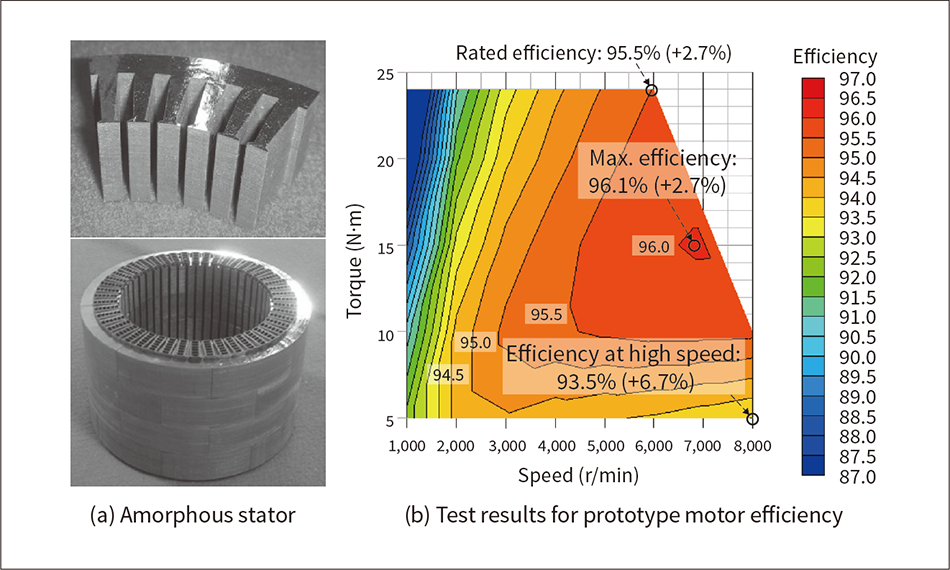 The stator is made by using a press to stamp out amorphous metal foil that is then adhesive-laminated to form a block. Efficiency testing of a prototype motor made using this amorphous metal demonstrated its superior performance to a motor made from conventional silicon steel sheet over the entire range.
Inverter Technology
Use of Double-sided Cooling to Increase Output Density
Figure 4 — Comparison of Power Module Cooling Techniques
 The cooling of automotive power modules has evolved in the past from single-sided cooling using thermal grease to direct water cooling that does away with the thermal grease layer to reduce thermal resistance. The main method used now is double-sided cooling, which increases the surface area for heat dissipation.
Among the measures needed to accelerate the adoption of electrified vehicles are miniaturization and higher output to facilitate installation and improve power consumption, and higher voltages to improve charging time and other performance criteria. Along with the advances in power semiconductors that have been ongoing since the 1980s, low-inductance wiring for rapid current interruption and techniques for improving the cooling performance of power modules are also among the factors driving progress toward higher output densities. While recent power modules use power semiconductors such as insulated-gate bipolar transistors (IGBTs) and silicon carbide (SiC) devices that feature low conduction resistance and allow small chips to carry heavy currents, the smaller mounting footprint of the power modules has got to the point where a trade-off is starting to emerge. That is, the performance inherent in these power semiconductors cannot be put to full use because the cooling systems are unable to dissipate enough heat, lacking the necessary thermal diffusivity and cooling surface area. Hitachi has responded by developing a new double-sided direct cooling technique that ensures sufficient cooling fins can be located close to the power semiconductors, reducing thermal resistance by 50% compared to the previous model (see Figure 4).
The technique works by housing the power semiconductors and power wiring among cylindrical metal cooling fins and immersing them in fluid coolant. The resulting eddy currents in the fins generate an opposing magnetic flux that counteracts the magnetic flux due to the current in the wiring, thereby canceling out the electromagnetic energy. This has succeeded in reducing wiring inductance by 40%, allowing the SiC and other high-speed power semiconductors to exhibit their full performance(3).
Reduced Charging Time Using New Insulator Structure
Figure 5 — Diagram of Old and New Structures and Graph of Relationship between Voltage and Insulation Life
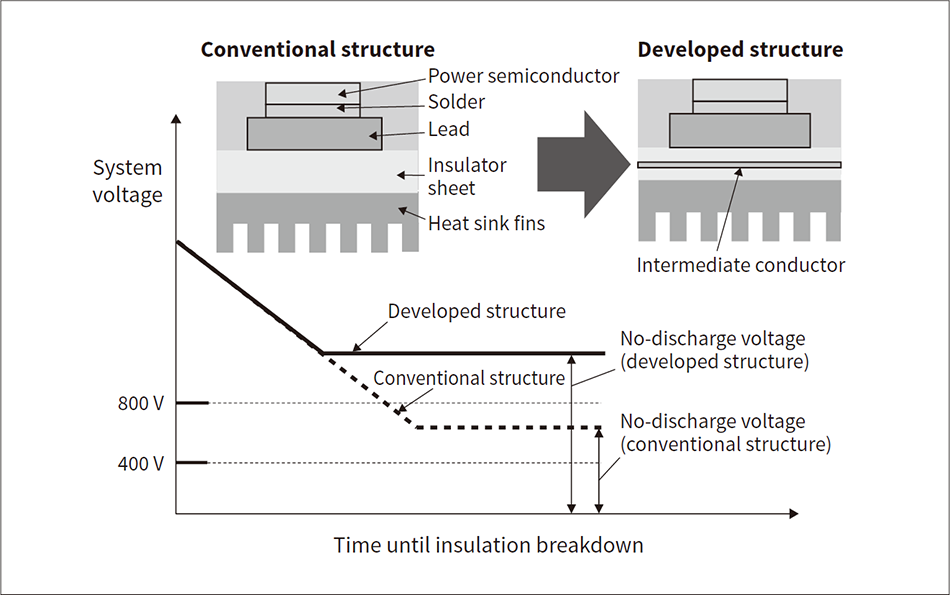 The new structure uses an intermediate conductor to spread the voltage across the insulator sheet, allowing higher voltages without discharges. This enables the voltage to be doubled while still using a sheet thickness that provides roughly the same heat dissipation as before.
While EV battery capacities have been increased over recent years to extend vehicle range, this has brought concerns about having to wait for charging and that charging times are much longer than it takes to fuel a gasoline car. Fast charging is made easier by using high-voltage systems that can transfer a larger amount of energy in a given time. Unfortunately, the difficulty of achieving low losses in conventional automotive inverters and of combining high heat dissipation with insulation that can withstand high voltages has meant that EV system voltages have remained at around 400 V.
Insulation and heat dissipation have in the past been achieved by using ceramic sheet with high thermal conductivity or plastic insulating sheets formed by mixing ceramic powder with adhesive. The problems with this have been the difficulty of making thin ceramic sheet and the potential for insulation breakdown due to corona discharges in air voids formed during the adhesion process.
In response, to halve the voltage across air voids in the insulating sheets and thereby facilitate the switch to 800-V systems that can perform charging in half the time, Hitachi has succeeded in doubling insulation performance and reducing thermal resistance by sandwiching intermediate conductive layers between insulating sheets that have been made thinner, thereby reducing the concentration of electric fields at air voids by spreading the applied voltage more uniformly. Inverters with a high output density of 94 kVA/L are already in full-scale production(4) (see Figure 5).
Power Conversion Incorporating Interoperation between Renewable Energy and Electrical Systems
Integrated Control of Supply and Demand that Links Consumers to Renewable Energy Generation
Along with the large-scale adoption of renewable energy, decarbonization will also require the establishment around the world of capacity for reliably supplying the high levels of electric power (in the hundreds of kilowatts) needed for the rapid charging of electric vehicles. In urban areas, ways of limiting the peak loads from air conditioning, elevators, and the rapid charging of EVs will become more important than ever, with reducing the cost of electricity to consumers being among the issues along with grid stability. Outside city centers, while more renewable energy will be installed, the challenge will be how to efficiently link power generation operators who want to trade renewable energy at high prices with consumers who want to increase the percentage of energy they obtain from zero-emission sources.
Accordingly, renewable energy generation sites and consumer sites need to be able to limit peak loads through the integrated control of supply and demand, utilizing practices such as the use of independently operated power lines to redistribute electric power and using power conditioning systems (PCSs) for energy storage. This integrated control of supply and demand works by predicting the availability of renewable energy generation based on past patterns of power supply and the patterns of power demand from consumer equipment, using the available power conversion equipment, electricity storage, and independently operated power lines to control the allocation of electric power in the way that best balances supply and demand while also minimizing the electricity cost (see Figure 1).
High-frequency SST Technology for DC Power Distribution
Figure 6 — Diagram of Modular Power Converter Incorporating SSTs
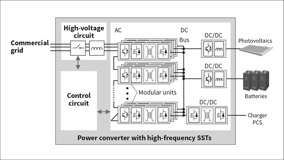 The modular power converter is built by series-connecting AC/DC converters with high-frequency isolation that can withstand the mains power grid voltage. This saves space by avoiding the need for a commercial transformer.
Amid the ongoing shift toward local sourcing of renewable energy, the distribution of this electric power has a need for compact PCSs that can be retrofitted in existing equipment in both urban and non-urban areas, and for commercial transformers to be made significantly smaller by using high frequencies to isolate them from the mains power grid, thereby downsizing the equipment and avoiding duplicate investment.
Electrical conversion systems fitted with modular high-frequency solid state transformers (SSTs) for high-frequency isolation are able to connect a wide variety of loads and power sources by combining different numbers of modules into blocks. These conversion systems can minimize the converter losses that occur when routing electric power, with the potential for efficiency improvements of 2 to 5% when transformer efficiency is also factored in. The modular units combine small size and light weight with high efficiency by using IGBTs for conversion between alternating current (AC) and direct current (DC) and SiC devices for DC/DC conversion, with these being interconnected via a high-voltage/high-frequency transformer operating at 50 kHz. By eliminating the need for a conventional transformer, it is anticipated that the new electrical conversion system with high-frequency SSTs will roughly halve the converter installation footprint compared to conventional models(5) (see Figure 6).
Conclusions
This article has described steps toward achieving widespread electrification in ways that deliver both environmental and social value, covering techniques for making motors more efficient, inverter technologies to dispel concerns about charging, and the use of high-frequency SSTs in power conversion to encourage greater use of zero-emission energy sources.
By further enhancing these core technologies, Hitachi intends to continue supplying products that reduce the burden on the environment with the aim of achieving carbon neutrality in 2050.
REFERENCES
- 1)
- T. Hara et al., “Vibration Reduction of Permanent Magnet Synchronous Motor Driven by Synchronous PWM Control with Carrier Wave Phase Shifts,” The Papers of Joint Technical Meeting on Magnetics, Motor Drive, and Linear Drive, The Institute of Electrical Engineers of Japan, MD-20-172, pp. 89–94 (Dec. 2020) in Japanese.
- 2)
- M. Sawahata et al., “Study of the High Space Factor Motor Using the Welding-less Rectangular Coil,” The Papers of Joint Technical Meeting on Magnetics, Motor Drive, and Linear Drive, The Institute of Electrical Engineers of Japan, MAG-20-084, pp. 25–30 (Dec. 2020) in Japanese.
- 3)
- A. Namba et al., “Next Generation High Power Density Electric Components Technologies,” Journal of the Japan Institute of Electronics Packaging, Vol. 19, No. 5, pp. 321–324 (Aug. 2016) in Japanese.
- 4)
- A. Hatanaka et al., “High Voltage and High Power Density Technologies for Inverter in Vehicle,” The Proceedings of the Society of Automotive Engineers of Japan 2021 Annual Congress (Spring), 20205033, No. 14-20, pp. 1–6 (May 2020) in Japanese.
- 5)
- M. Nakahata et al., “Development of a Control Method for LLC Converter Utilized for Input-Parallel-Output-Series Inverter System with Solid-State Transformers,” IEEJ Journal of Industry Applications, Vol 8, No. 4, pp. 652–659 (Jul. 2019).

