Development of Advanced Measurement Technologies and Their Application to Decommissioning of Fukushima Daiichi Nuclear Power Station
Highlight
Decommissioning of the Fukushima Daiichi Nuclear Power Station requires work in a highly radioactive environment, making it essential to use robots that can be operated remotely. To meet this need, Hitachi Group developed and applied robots for use at the site that can perform work such as debris removal and decontamination, and various inspections such as visual inspections, ultrasound inspections, and radiation inspections underwater and in the air. Measurement technologies used in the inspection work needed to be mounted on these robots. This article describes the advanced measurement technologies that were developed for Fukushima Daiichi Nuclear Power Station, including robot self-position estimation and posture estimation technologies, radiation measurement technology, and ultrasound sensing technology.

Introduction
In the decommissioning of the Fukushima Daiichi Nuclear Power Station (hereinafter “1F”), heavy work such as debris removal and decontamination, and work such as visual inspections, ultrasound inspections, and radiation inspections underwater and in the air must be performed in a highly radioactive environment. In response to this challenge, Hitachi Group developed robots for various types of inspection work that can be operated remotely, and applied them to decommissioning work at 1F(1). These robots need to be equipped with the measurement technologies used in inspection work, in addition to the end effectors for heavy work and state sensing technologies for controlling the robots.
This article describes the advanced measurement technologies that were developed for these robots to operate them in the highly radioactive environment of 1F. These include robot self-position estimation and posture estimation technologies; radiation measurement technologies such as an optical fiber type gamma ray dose rate meter and neutron measurement; and ultrasound sensing technology for visualizing underground conditions, including fuel debris.
Technologies Supporting Remote Work in Highly Radioactive Environments
Robot Position Estimation
To be able to operate a robot remotely, the robot’s current position must be identified and reflected in its operation. Furthermore, when a robot is used for inspections, data from measuring instruments such as a mounted radiation detector or underwater camera must be linked to the robot’s position. Although accurate robot positioning is required, adding a measuring instrument for estimating the position of inspection robots is difficult. This is because the size of the robots used inside locations such as 1F’s primary containment vessel (PCV) is restricted due to the robots’ need to pass through narrow spaces.
As a solution, Hitachi developed a robot position estimation method that uses the two cameras that are already mounted on the robot. In this method, the robot’s initial position is identified by calculating its position and posture relative to the structure, whose layout has already been mapped by stereo camera. Then, as the robot makes repeated changes in its relative position from the initial position, the current position is estimated by tracking the structure. The developed position estimation method was applied to an internal inspection of 1F’s Unit 1 containment vessel that was performed in March 2017(2) (see Figure 1).
Figure 1 — Position Estimation Method Applied to Internal Inspection of Unit 1 Containment Vessel at 1F The two cameras mounted on the robot are used to identify the robot’s initial position by calculating its position and posture relative to the structure, whose layout has already been mapped with stereo cameras. Then, as the robot makes repeated changes in its relative position from the initial position, the current position is calculated by tracking the structure.
Robot Posture Estimation
Figure 2 — Example Configuration for Remote Operation Support System A robot with no mounted sensor (sensor-less robot) and stereo cameras are placed in the work area. In the operation area, the controller estimates the robot state based on the stereo camera images.
In addition to the position estimation described in the previous section, when controlling a robot for remote work, the posture of the robot, such as the hand and arm positions, must be identified and reflected in the robot’s operation. However, because the robots used for work at 1F need to be controlled by an operator in an area with low radiation away from the work area, the operator cannot directly observe the robot during operation. Therefore, a system is required that supports the real-time operation and monitoring of the robot. However, the regular configuration where a posture measurement sensor is mounted on the robot itself for monitoring cannot be applied in a high-radiation environment due to problems related to protecting the equipment against radiation.
In response to this issue, Hitachi developed a remote operation system that operates and monitors the robot using information from sensors that are installed in an external location instead of on the robot itself(3).
Figure 2 shows an example configuration for the developed remote operation support system. A robot with no mounted sensors (sensor-less robot) and stereo cameras are installed in the work area. In the operation area, the controller estimates the robot state based on the stereo camera images. The results are shown to the operator in a virtual environment, enabling the operator to confirm the three-dimensional (3D) shapes and positions in the work area with an accuracy that is impossible using only camera images. This supports operations such as providing access to the work target and avoiding interference with surrounding structures.
Visualization of Underwater Environment Using Ultrasound
Figure 3 — Principle of Ultrasonic Vision and Example of Visualization Results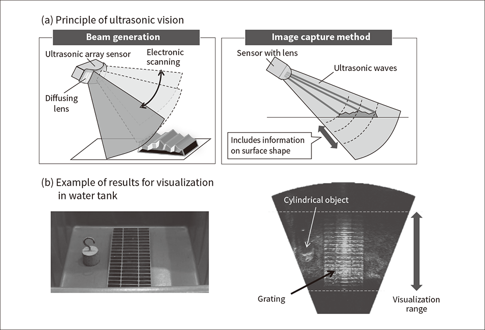 The image range is expanded by mounting a diffusing lens on an ultrasonic array sensor comprised of multiple oscillators, scanning the ultrasonic beam in the lateral direction electronically and with a delay time setting, and enlarging the beam width in the vertical direction with the diffusing lens.
Inspections and other work in areas with accumulated water are likely to be conducted in murky environments that prevent viewing with optical cameras. Hitachi developed technology that uses ultrasound to visualize underwater environments, with the goal of enabling the targets of such environmental inspections and work to be checked and monitored.
Compared to visible light, ultrasonic waves have higher transmission in water, but it is difficult to capture a wide range of images for them in real time. To resolve this issue, Hitachi applied phased array technology that was developed for non-destructive inspections at nuclear power plants.
Figure 3 (a) shows the principle of ultrasonic vision, and Figure 3 (b) shows an example of the visualization results. The image range was expanded by mounting a diffusing lens onto an ultrasonic array sensor comprised of multiple oscillators, scanning the ultrasonic beam in the lateral direction electronically and with a delay time setting, and enlarging the beam width in the vertical direction with the diffusing lens. The results of a performance evaluation test in a water tank confirmed that the target (grating grid width) was visible at a resolution of approximately 20 mm.
Measurement Technologies for Inspecting Fuel Debris and Sediment
Optical Fiber-type Gamma Ray Dosimeter
Figure 4 — Compact Radiation Dosimeter Mounted on PMORPH By detecting the light emitted by a garnet crystal with a diameter of 2 mm that is mounted in the sensor unit, radiation resistance is provided that is 10,000 times stronger than the conventional silicon semiconductor method.
To inspect the fuel debris directly under the nuclear reactor, a radiation detector was required that could be controlled remotely and could operate stably for a long time even in a high-radiation and narrow-space environment. To meet this need, Hitachi developed a compact gamma ray dosimeter equipped with an optical fiber and a crystal that emits light when exposed to radiation, and which can be mounted on PMORPH(4), a robot used to inspect the inside of a nuclear reactor’s containment vessel.
Figure 4 shows the compact radiation dosimeter mounted on PMORPH. By detecting the light emitted by a garnet crystal with a diameter of 2 mm that is mounted in the sensor unit, radiation resistance is provided that is 10,000 times stronger than the conventional silicon semiconductor method. This radiation dosimeter was applied to inspections inside the containment vessel of the 1F Unit 1 reactor in March 2017, and the radiation dose rate and images were successfully captured(5). This dosimeter is scheduled to be installed on equipment in the next inspection, and will continue to contribute to the detailed assessment of the conditions inside the nuclear reactor.
Inspection Technology for Underwater Environments
A past inspection (March 2017) identified sediment in the underground level below the 1F Unit 1 reactor containment vessel. To enable the future removal of the fuel debris, detailed checking of the conditions in this underground level, including the sediment, is essential. Since the underground level is underwater, a plan was formulated to capture detailed information about the conditions using remotely operated vehicle (ROV) inspection devices that can move around underwater and are equipped with various measuring instruments.
Figure 5 shows the various measuring instruments mounted on these ROVs(6). The following ROVs are scheduled to be used for sediment inspections inside the 1F Unit 1 reactor containment vessel in 2022.
- Underwater inspection using ultrasound
ROV-B is equipped with a scanning ultrasonic rangefinder and water temperature meter for obtaining point cloud data for the sediment surface across a wide range outside of the pedestal, thus capturing the 3D height distribution. An anchor installed at the center of the ROV bottom surface stabilizes its posture, and an ultrasonic rangefinder of approximately 2 MHz performs two-dimensional (2D) scanning by combining ±50° mechanical scanning using a mechanical tilt mechanism with ±50° electronic scanning in the direction perpendicular to the tilt direction. This enables measurement of the 3D shape.
Meanwhile, ROV-C uses a high-output ultrasonic sensor of approximately 100 kHz to measure the depth of sediment around the outside of the pedestal, and the height of the floor surface and fuel debris under the sediment (lumps and powder layers with high specific gravity). At this time, to enable deep layers in the sediment and other substances to be inspected, a high voltage several times the normal level is applied to the ultrasonic sensor. Unlike ROV-B, ROV-C performs inspections in the straight-down direction; therefore, the depth distribution in the horizontal direction is estimated by moving ROV-C. - Radiation measurement technology for inspecting fuel debris
ROV-D is a device for inspecting the radiation unique to fuel debris. To enable mounting on ROV-D, Hitachi developed radiation measurement technology that can implement nuclide analysis at the same time as gamma ray measurement and neutron flux measurement, even in highly radioactive environments exceeding 10 Gy/h. By adopting a digital signal processing method that can detect the minute electrical load of the radiation sensor in environments that are both highly radioactive and exposed to electrical noise caused by ROV, radiation resistance was achieved at a level about 200 times stronger than conventional radiation measurement technology.
Figure 5 — Various Measuring Instruments Mounted on Underwater ROVs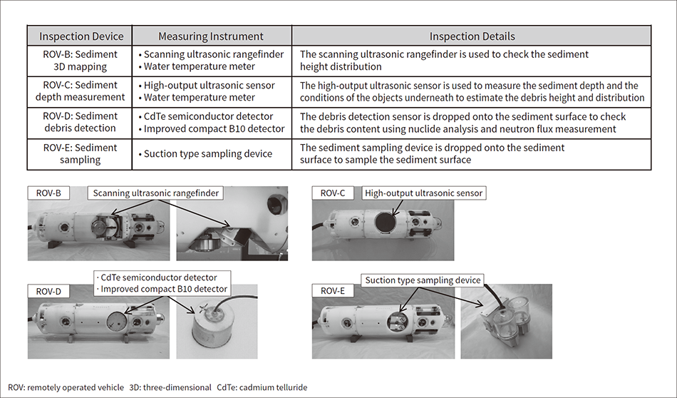 Inspection devices (ROVs) that can move around underwater are equipped with various measuring instruments to obtain information related to underground sediments. Ultrasonic sediment 3D mapping, sediment depth measurement, sediment debris detection, and sediment sampling can be performed.
Conclusions
This article has described the advanced measurement technologies that Hitachi developed and applied to robots to enable them to be operated in highly radioactive environments for the decommissioning of 1F. These include robot self-position estimation and posture estimation technologies; radiation measurement technologies such as an optical fiber type gamma ray dosimeter and neutron measurement; and ultrasound sensing technology for visualizing underground conditions, including fuel debris.
These technologies can be utilized in work such as inspections, environmental improvements, and fuel debris removal. In the future, these technologies will be further developed to support the decommissioning work over the long term.
Acknowledgments
The devices described in this article were developed using robot technologies and measurement technologies from Hitachi Group. Of these, the robot position estimation technology, compact radiation dosimeter, and radiation measurement technology for inspecting the radiation unique to fuel debris were developed as part of projects undertaken by the International Research Institute for Nuclear Decommissioning and funded by the Agency for Natural Resources and Energy through the FY2013 grants for the Technology Development Project of Decommissioning and Safety Technology and so on, and the FY2013 to FY2018 supplementary budgets for the Project of Decommissioning and Contaminated Water Management.
REFERENCES
- 1)
- S. Okada et al., “Development and Application of Robotics for Decommissioning of Fukushima Daiichi Nuclear Power Plant,” Hitachi Review, 69, pp. 556–563 (Jul. 2020).
- 2)
- Tokyo Electric Power Company Holdings, Inc., “Unit 1 Primary Containment Vessel (PCV) Investigation” (Mar. 2017) in Japanese(PDF Format, 2.93MByte)
- 3)
- Hitachi-GE Nuclear Energy, Ltd. et al., “Manipulator Pose Estimation System Using Stereo Camera for Decommissioning Work,” E-Journal of Advanced Maintenance, Vol. 11, No. 1, NT93 (May 2019).
- 4)
- S. Okada et al., “Development of Internal Investigation Device for Primary Containment Vessel: Shape Changing Robot ‘PMORPH’,” Electrical Review, Vol. 641, No. 102, pp. 27–31 (Jun. 2017) in Japanese.
- 5)
- K. Ueno et al., “Fiber Optic-Type Dosimetry for Remote Measurement of Dose Rate Distribution in High Radiation and Narrow Environment,” Journal of the Atomic Energy Society of Japan ATOMOΣ, 62, pp. 717–721 (Dec. 2020) in Japanese.
- 6)
- International Research Institute for Nuclear Decommissioning et al., “Progress of Preliminary Work for Unit 1 Primary Containment Vessel (PCV) Investigation,” (Oct. 2020) in Japanese(PDF Format, 4.51MByte)

